Last update: 30-12-2022 18:14. This blog post will be updated on a regular basis
Last week I bought a 737 CDU and throttle quadrant for a great price. The throttle quadrant is not motorized, but I’ll try to make it motorized myself with stepper motors. First of all the trust levers are on the move. After that, the speed brake lever should also be motorized.
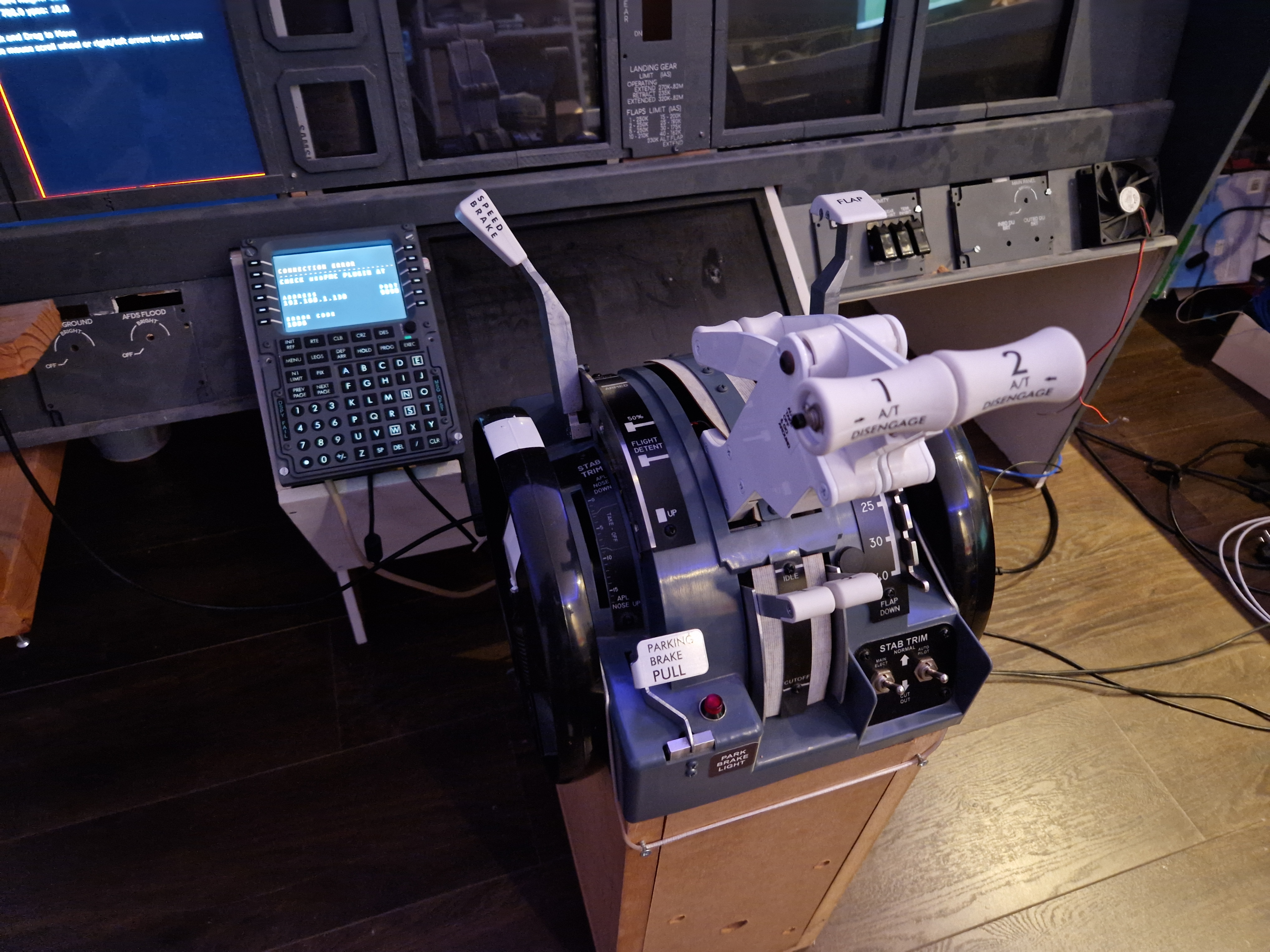
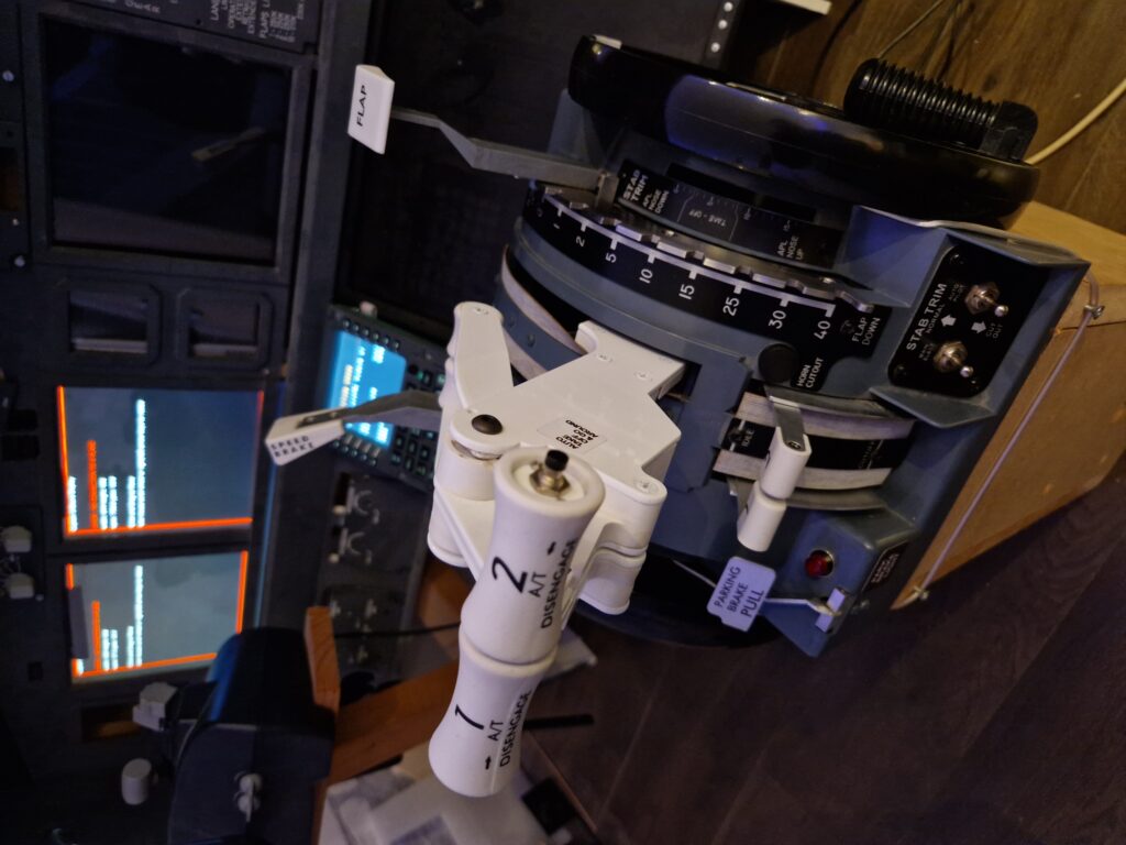
Today, I gave it a try to disassemble the throttle body and that is a hard challenge. A video will follow later. You should disassemble the trims first, then you can unscrew the screws on the side. After that, you also need to disassemble all the outside body parts (trust lever body, speed brake lever body and flaps lever body). When the screws on the bottom plate are unscrewed, the throttle body can be lifted. What’s left is a nice inside frame.
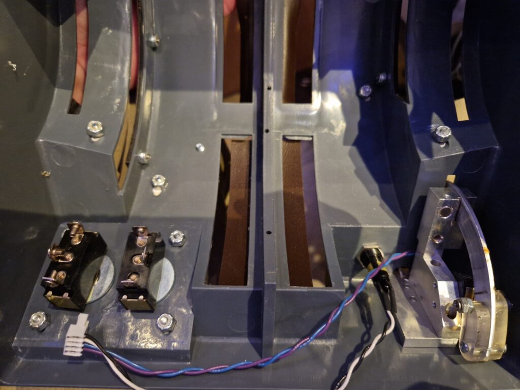
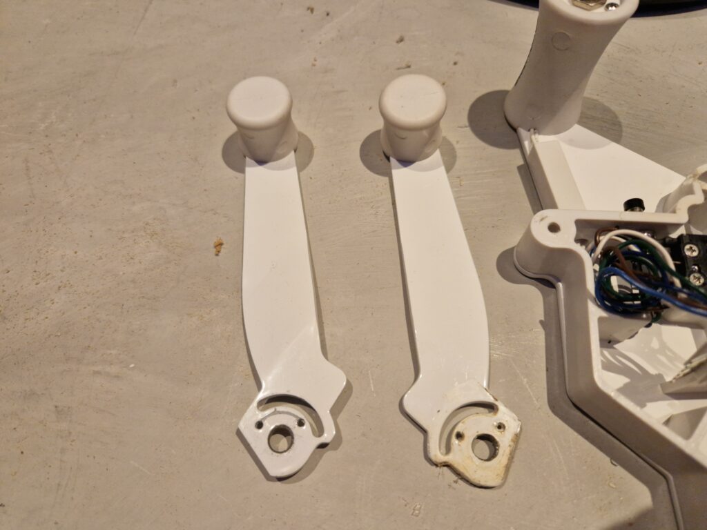
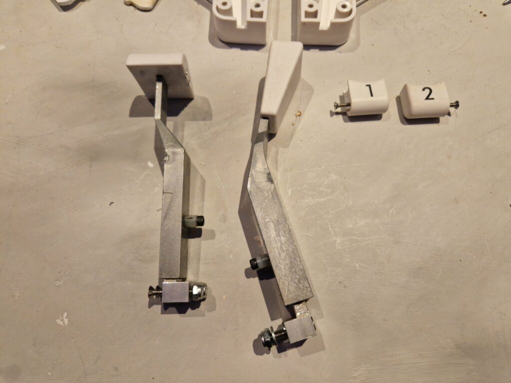
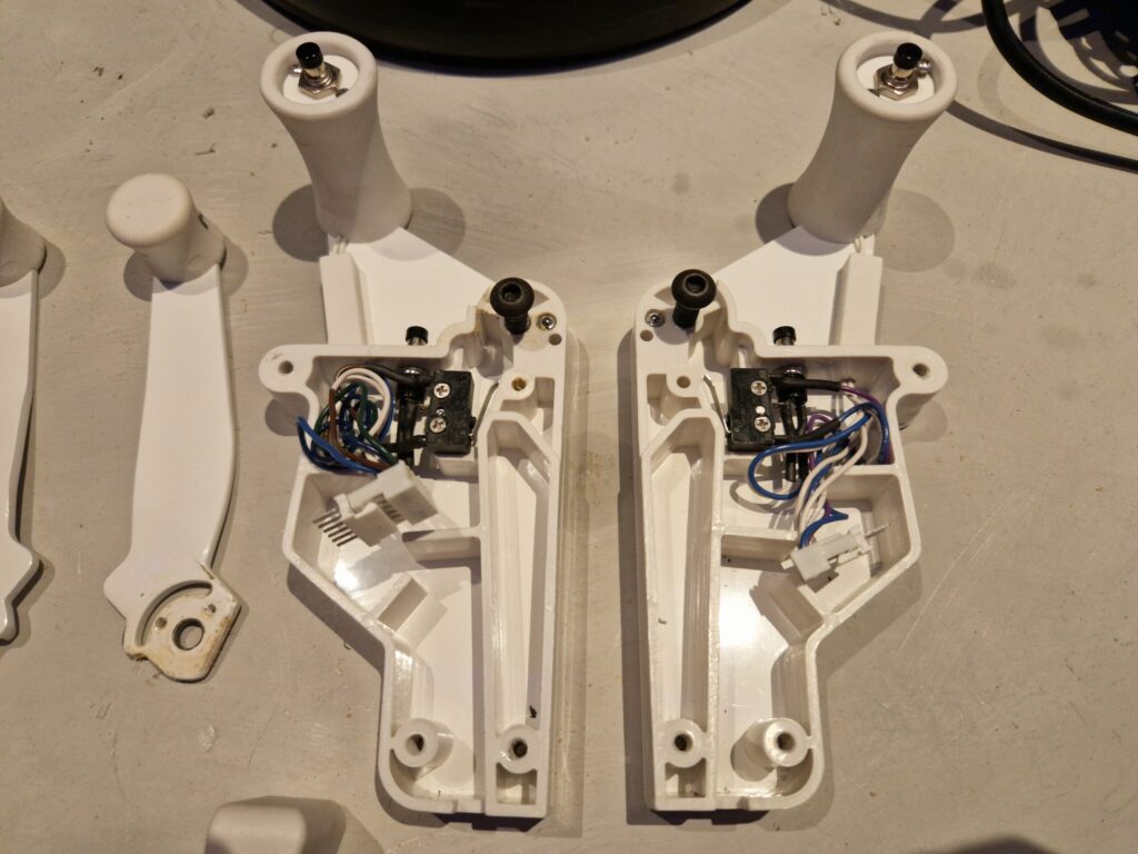
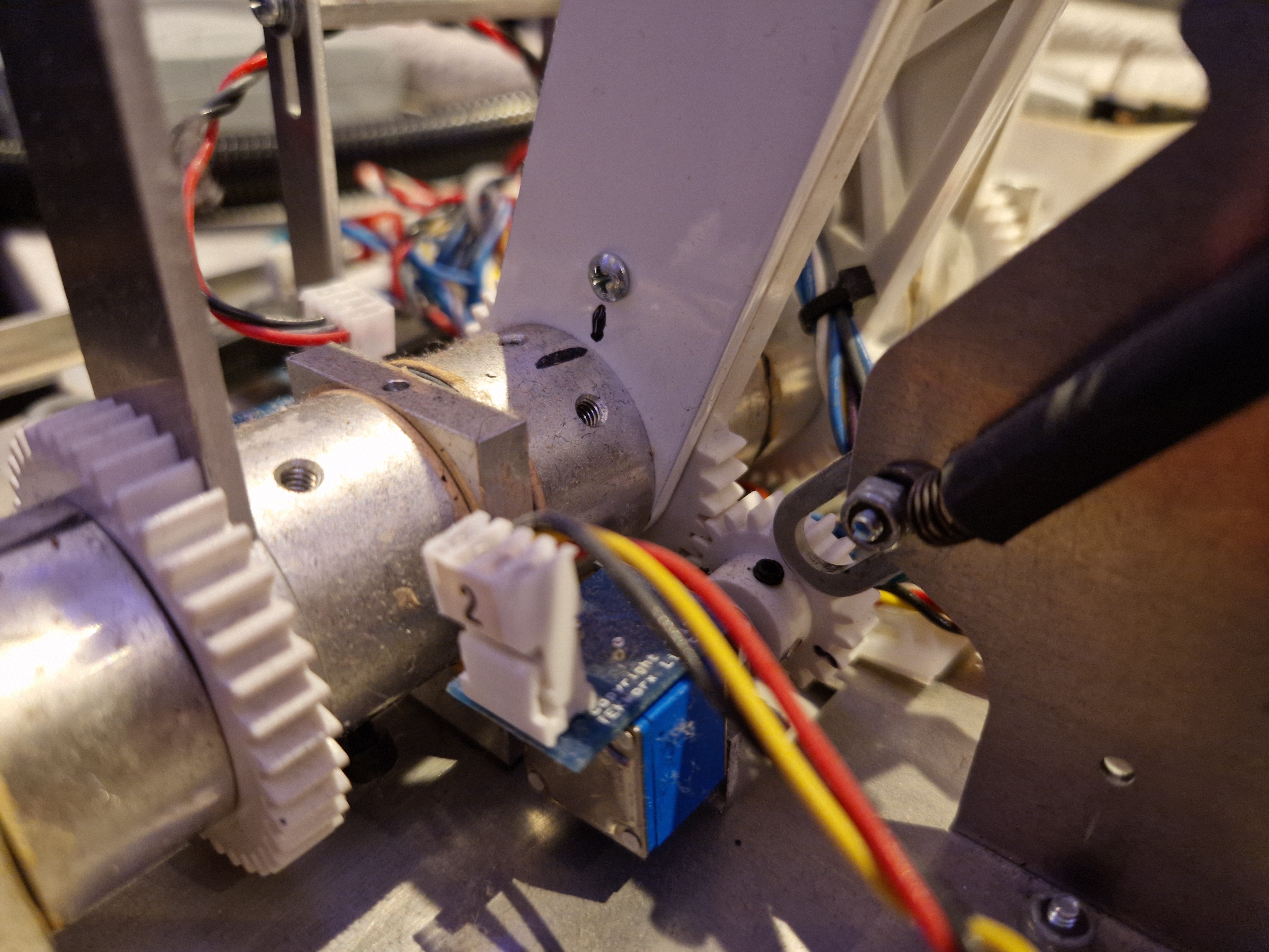
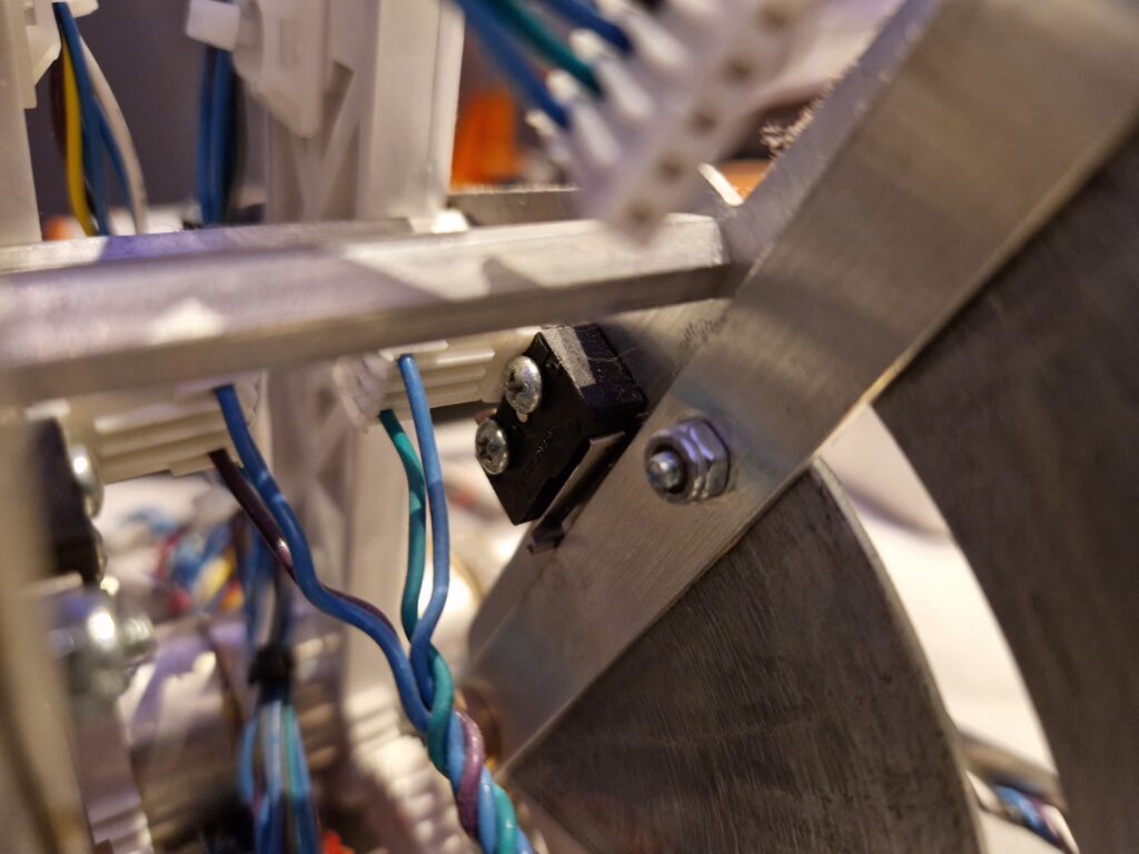
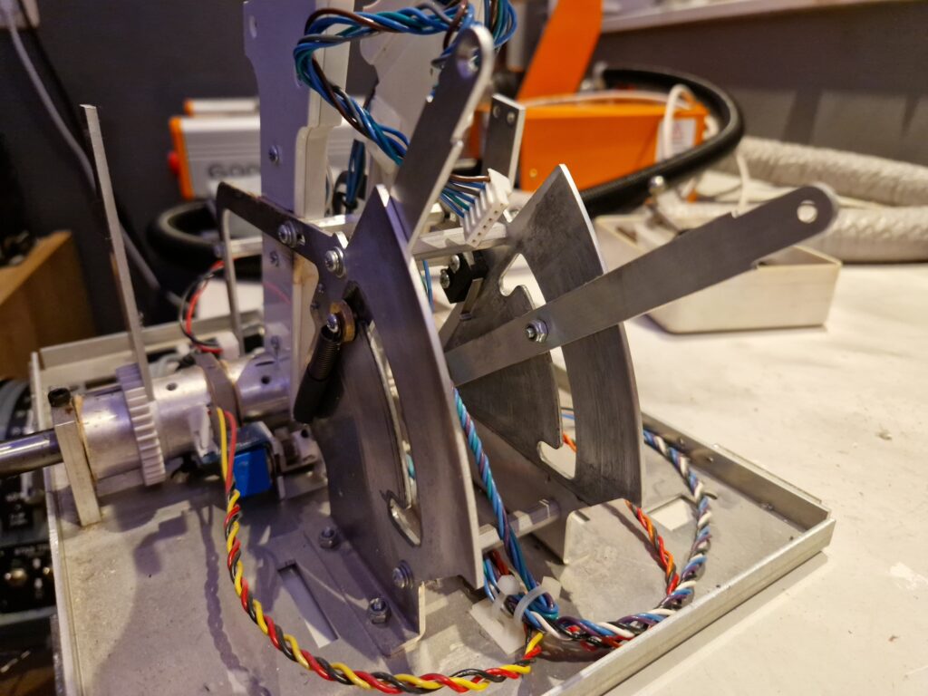
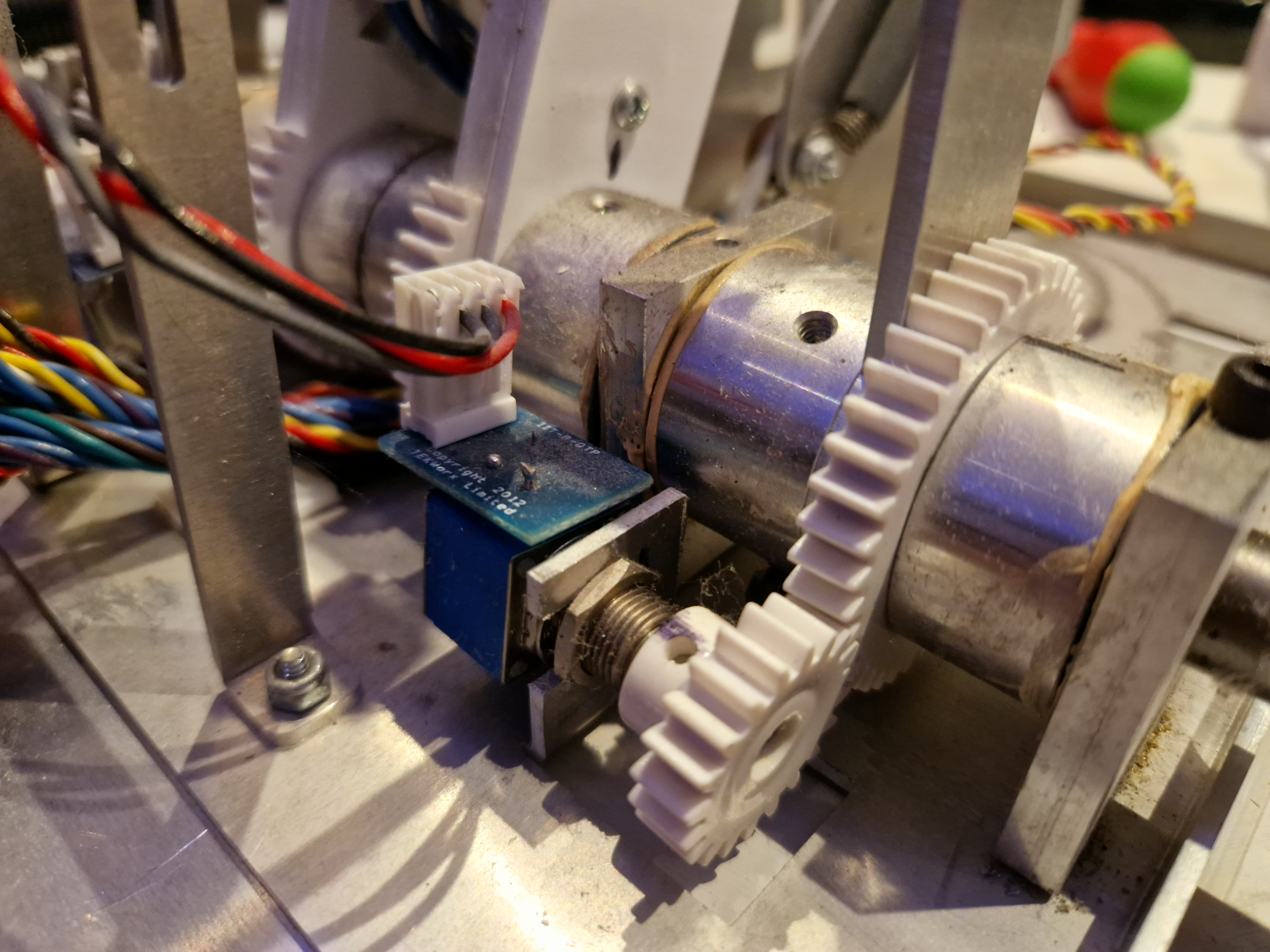
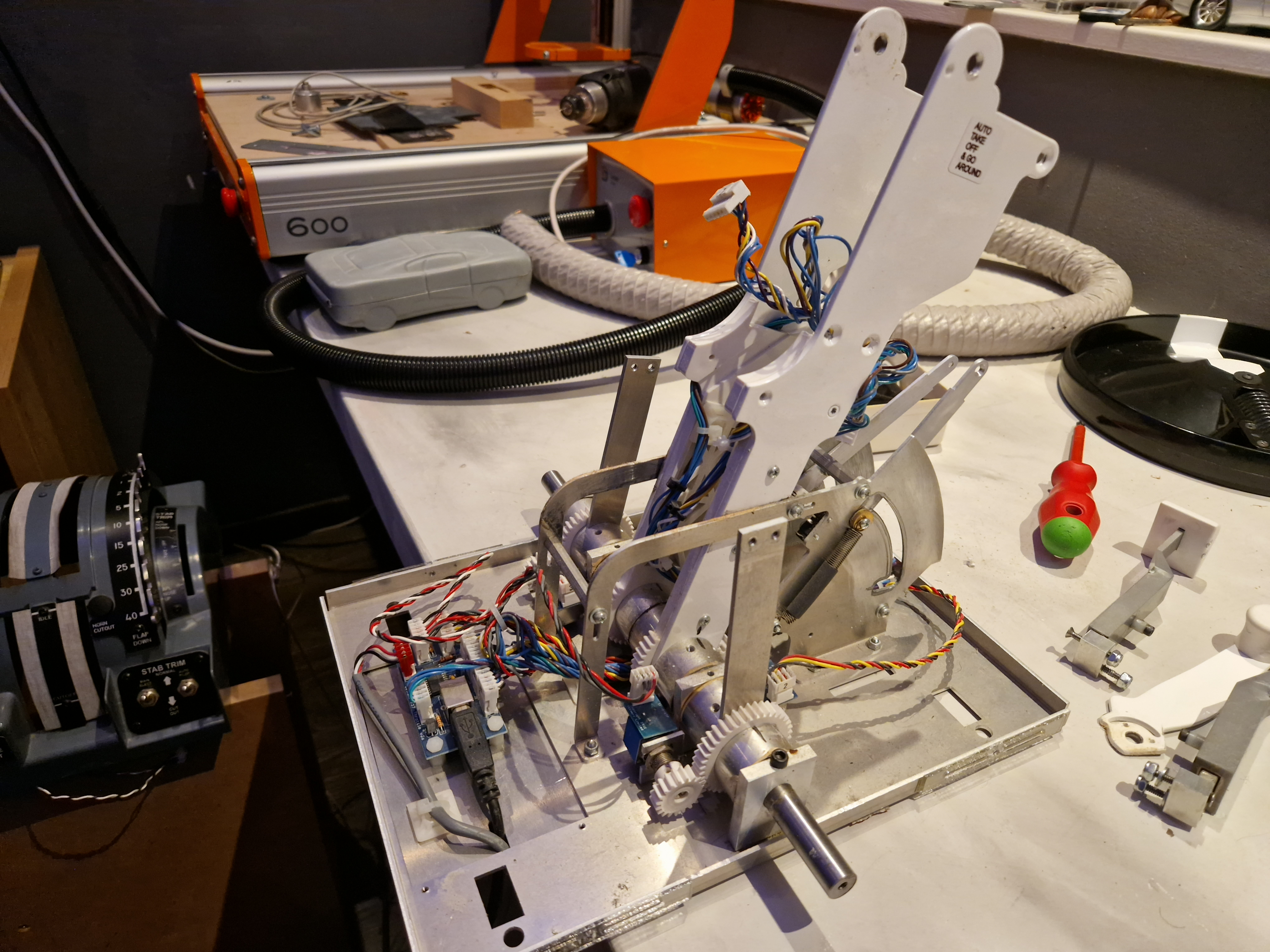
There is more than enough space to build some stepper motors inside. Before I do this, I need to create a design and measurements to decide the best place. Maybe I need to 3D print some supports.
Update 9-12-2022
Currently, I’ve got two types of stepper motors, the 28BYJ-48 and the Nema 17 (datasheet). The first one is a relative weak and slow motor for this case (300gf/cm, 15rpm against 4200gf/cm, 600rpm for the Nema 17). The 28BYJ-48 is mostly used in devices like motion camera’s for example. You like to have a more powerful motor so that when you have your hand on the lever, it will still move the lever. With that in mind, the Nema 17 will do the job, so I like to use that one.
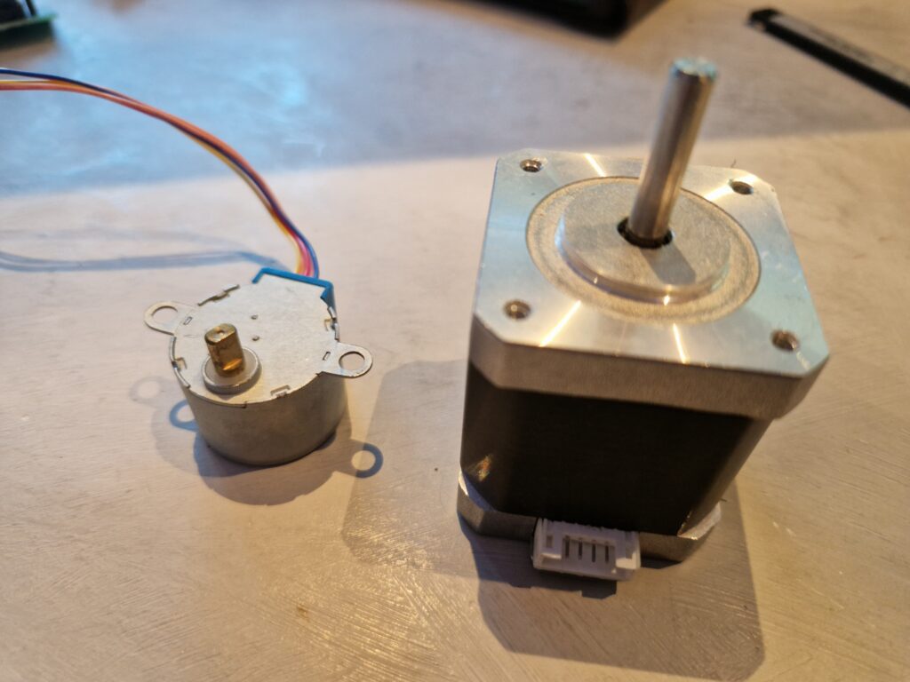
At the moment there is only one problem. I do not have the DVR8825 driver boards to control them correctly, so I’ve ordered them together with a set of plastic gears. Until it’s delivered I will figure out how I can make changes that fit in the current construction and make some prototypes. I can eventually use my CNC to generate some gears myself.
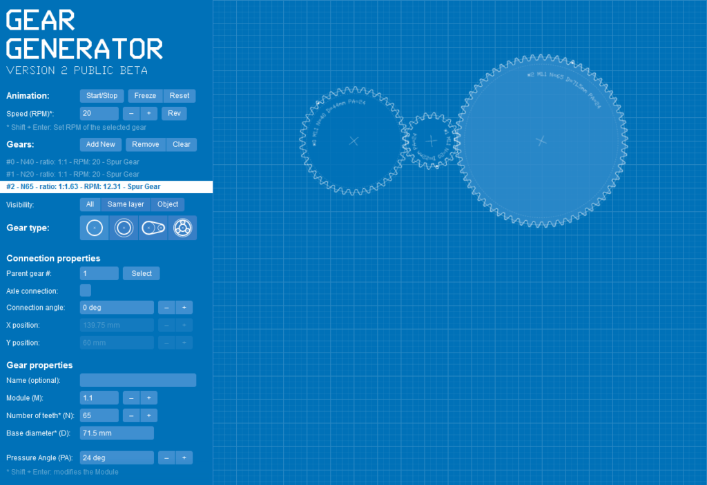
It’s a bit hard to find a great solution since I’m not an mechanics engineer, but I have to do something with gears and that requires some mathematics. Lucky enough there is an online tool to simulate gears.
The bottom of the throttle is a solid metal plate, which is harder to customize. I like to play around first, so I’ll create a new wooden buttom plate with my CNC, so I can create more holes, cutouts etc. Before I can do that, I need to design one in Fusion 360.
I think I’ll start with the speed brakes lever, which needs to move very fast. The speed brake lever is easier to reach, so it may be easier to customize. The lever has one gear of 40 teeth with a diameter of 45mm that drives another gear of 20 teeth, 23mm diameter. The 20 teeth gear is attached to a Bourns 81A1A-B28-A15L potentio meter.
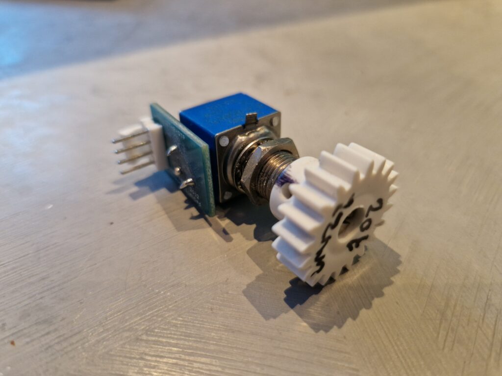
So what we will do next is CNC some gears to first test what gear fits best and CNC the new prototype wooden bottom plate.
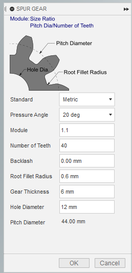
In Fusion 360, you can use the “SpurGear” add-in to generate gears. For the existing gears, these parameters can be used:
Update 30-12-2022
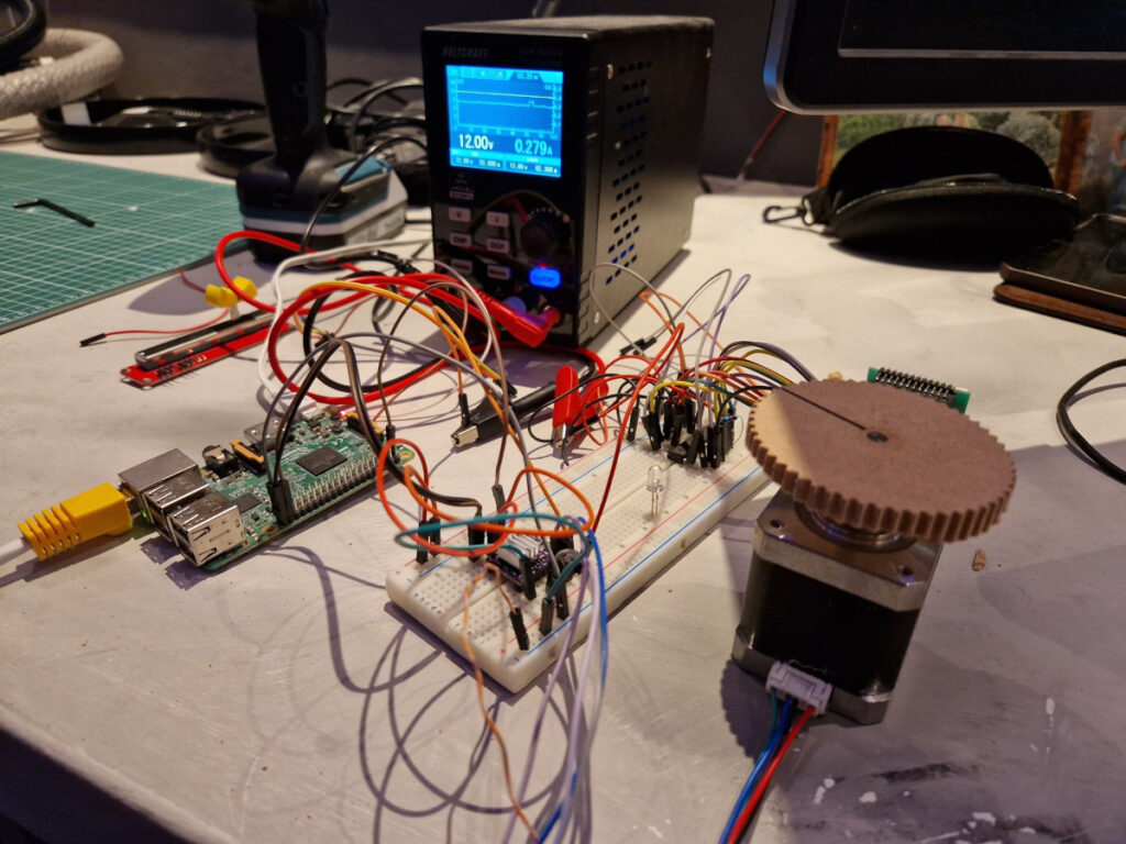
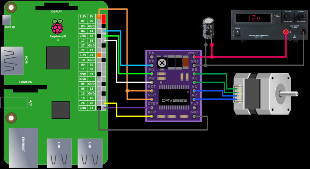
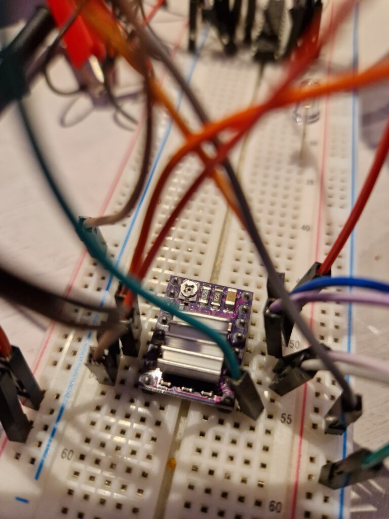
So I’ve received the DRV8825 stepper motor driver. It’s time to prototype it first to check if I can get it to work. Different articles on the internet says to use a 100V electrolytic capacitor between the 12V VMOT and GND of the stepper motor driver, but of course I don’t have any yet, so ordered them directly. In the meantime, I’ll continue prototyping anyway and will follow the following picture, but with a prototype board:
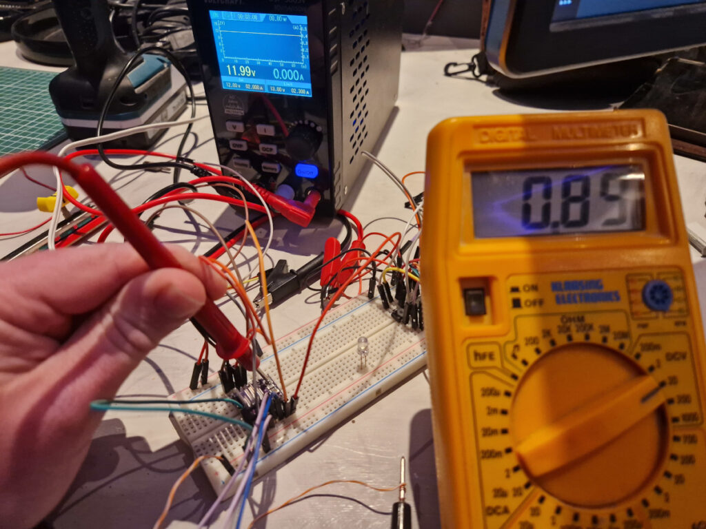
Before connecting the stepper motor, the stepper motor Vref needs to be adjusted to protect the current to the stepper motor. To do this, we’ll use a multimeter. Again, disconnect the stepper motor, connect the ground of the multimeter (black wire) to a GND of the driver board and use a small screw driver to adjust the potentiometer on the driver board. While adjusting, touch the V (red wire) of the multimeter to the screw driver, so you can check the adjustment directly.
The value of the potentiometer should be calculated with the following formula: I(limit) = V(ref) x 2. The stepper motor I use is a 2.7V, 1.8A motor (it will be powered by a 12V power supply). So the potentiometer voltage should be adjusted to a value of 1.8A / 2 = 0.9V. When done, power off the power supply and connect the stepper motor. After that, power on the power supply again. Be sure to keep an eye on the heat. If you hear a high frequency tone, you may need to readjust the potentiometer and double check everything.
I’ve used the following Python code to control the stepper motor:
from time import sleep
import RPi.GPIO as GPIO

DIR = 20
STEP = 21
CW = 1
CCW = 0
SPR = 200 # 360 / 1.8 degree angle

GPIO.setmode(GPIO.BCM)
GPIO.setup(DIR, GPIO.OUT)
GPIO.setup(STEP, GPIO.OUT)
GPIO.output(DIR, CW)

step_count = SPR
delay = .005 # 1s / 200 SPR

for x in range(step_count):
        GPIO.output(STEP, GPIO.HIGH)
        sleep(delay)
        GPIO.output(STEP, GPIO.LOW)
        sleep(delay)

sleep(.5)
GPIO.output(DIR, CCW)
for x in range(step_count):
        GPIO.output(STEP, GPIO.HIGH)
        sleep(delay)
        GPIO.output(STEP, GPIO.LOW)
        sleep(delay)

print("cleanup")
GPIO.cleanup()
The stepper motor has a 1.8 degree angle per step, so for a full revolution, we need 360 / 1.8 = 200 steps per revolution (SPR).
With the delay, we can control a bit of the speed. Normally, you would calculate the delay by 1s / 200 SPR = .005s. When changing it to a higher delay (for example .020), the delay between every step takes longer, so you will notice hitches. This can be resolved, but in my case, the throttle lever will move slowly, so it’s not an issue for now.
